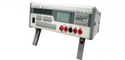
Overall dimensions, mm
96×48×95
Operating temperature range
From -40 to +50 °C (relative humidity 95% at +35 °C)
Basic error
Current and voltage: ±0,2 %, ±0,5 %; frequency: ±0,01 Hz, ±0,1 Hz; analogue output: ±0,5 %
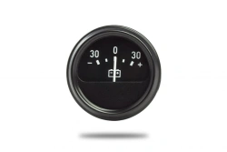
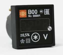
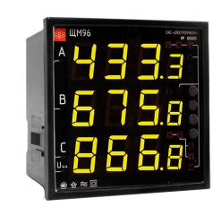
LED indication
1 block of seven-segment indicators (4 indicators per block)
Input signal
100 mV; 150 mV; 200 mV; 250 mV; 500 mV; 1000 mV; 2000 mV; 1 V; 2 V; 5 V; 10 V; 20 V; 50 V; 100 V; 150 V; 200 V; 250 V; 380 V; 500 V; 750 V; 2 mA; 5 mA; 10 mA; 20 mA; 50 mA; 100 mA; 200 mA; 500 mA; 1000 mA; 2000 mA; 1 A; 2 A. Connection via trans
Frequency range of measured / converted signals
45 to 65 Hz (default), 300 to 500 Hz (optional, when ordering)
Maximum reading range
0 to 9999
Galvanic isolation of output circuits, power supply circuits
Got it
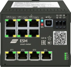
RS485 communication interface
Quantity: 1; Modbus RTU protocol
Analog outputs
Quantity: 0, 1, 2; Ranges: 0...5 mA, 4...20 mA, 0...20 mA, 0...2.5...5 mA, 4...12...20 mA, 0...10...20 mA
Discrete outputs
Quantity: 0, 1, 2; DC voltage 300 V, 100 mA or AC voltage 200 V, 100 mA
Power supply voltage
5VN - (5 +4/-0,5) VDC, 12VN - (12 +6/-3) VDC (there is protection against incorrect connection of the polarity of the supply voltage), 24VN - (24 +12/-6) VDC (there is protection against incorrect connection of the polarity of the supply voltage), 24VN - (
Power consumption from the power supply circuit, not more
3.2 B-A
Reprogramming
Via "Configurator" program (RS485 interface)
Degree of protection
IP50
Performances
General industrial; for operation at NPPs (safety class 4 according to NP-001-2015)
Inspection interval
10 years
Warranty period of operation
36 mos.
Average service life, at least
20 years
Height of indicator sign, mm
20